
Energy flow diagrams show what is happening to a particular type of energy as it is used or changed in some process or situation. Energy flow diagrams can be extended to include other forms of energy, such as light energy, heat energy and sound energy. Below is an example of an energy flow diagram for a light globe being powered by a wind generator. A CD player produces sound energy. Draw an ...
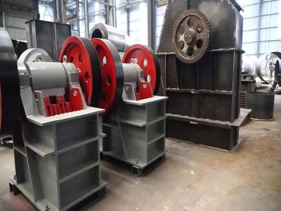
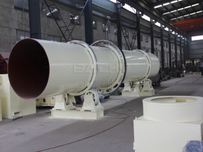
A wind turbine is a device that converts the wind's kinetic energy into electrical energy.. Wind turbines are manufactured in a wide range of sizes, with either horizontal or vertical axes. It is estimated that hundreds of thousands of large turbines, in installations known as wind farms, now generate over 650 gigawatts of power, with 60 GW added each year.

Fault trees and reliability block diagrams are both symbolic analytical logic techniques that can be applied to analyze system reliability and related characteristics. Although the symbols and structures of the two diagram types differ, most of the logical constructs in a fault tree diagram (FTD) can also be modeled with a reliability block diagram (RBD). You can use either diagram type or ...
Block diagrams are ideal for creating a highlevel overview of a system to account for major system components, visualize inputs and outputs, and understand working relationships within your system. Our block diagram maker is the ideal diagramming solution to help engineers tackle complex system overviews when designing hardware or software, implementing process improvements, and more. .
Click here for the same diagram using the Coleman Air C160/C160M controller. (Page ) Click here for a dual solar/wind diagram using the Coleman Air C440HVM controller. (Page 7) But I have a single phase (or D/C) Turbine Click here. (Page ) See our FAQ's for lots of great information. Available manuals for each product we sell can be downloaded from the product's detail page. HOME ...

Figure 8: NV block layout with Static Block ID enabled 32 Figure 9: Redundant NVRAM Block layout 35 Figure 10: Dataset NVRAM block layout 37 Figure 11: RAM Block States 50 Figure 12: UML sequence diagram NvM_Init 156 Figure 13: UML sequence diagram NvM_SetDataIndex 156 Figure 14: UML sequence diagram NvM_GetDataIndex 157 Figure 15: UML sequence diagram .

Windmill Diagram e lk horn s danish windmill was built in 1848 in norre snede denmark this mill and others like it in denmark and throughout europe were used to grind grain into flour for farmers in neighboring communities unfortunately the vast majority of mills of this kind called a smock mill are deteriorating throughout europe, a windmill is a structure that converts the ...

Create any type of block diagram with minimal effort. Draw even the most complex of block diagrams effortlessly with Creately's advanced features. Smart shapes and connectors, plus create, diagramming shortcuts and multiple styling options. Intuitive drag and drop interface with precision drawing and control.

Windmill Diagram Other Files Fiandaca Musco Diritto Penale Parte GeneraleFiji Seventh Form Examination Examiners ReportFifth Grade Science Electrical Circuit PowerpointFendt Favorit 610 LsFiat 65 66 DtField Manual Epm3 120Fce Gold Plus Exam MaximiserFema Is 1 A Answer KeyFdny Torch TestFender ChampFiji School Leaving Certifie 2013 Question PapersFiftyseventh Annual Report .
· Windmills have been used for centuries to harness the power of the wind. They are also charming decorative additions to a backyard or garden. While these windmills can't turn wind energy into electricity, they can add some whimsy to your...

· Well written NI LabVIEW appliions have block diagrams that are organized and easy for other programmers to read. The Block Diagram Cleanup utility was introduced in LabVIEW to help you automate the task of organizing code, and additional functionality to help preserve label loions and select the portion of code to be cleaned was introduced in LabVIEW 2009.
Then the area needs to be cleared of trees and other structures that may block wind. In some cases, a dirt mound or concrete base is erected to raise the windmill off the surface to ch more wind. Final assembly 7 The parts of the main body are connected first. They are bolted together on the ground and then raised up vertically. The outer poles are joined with the connecting rods. Clamps ...
The Block Definition Diagram in SysML defines features of a Block and relationships between Blocks such as Associations, Generalizations, and Dependencies. It captures the definition of Blocks in terms of properties and operations, and relationships such as a system hierarchy or a system classifiion tree. In addition, you can use a Block Definition Diagram to apply Constraint Blocks to ...

A block diagram for a system is not unique, meaning that it may be manipulated into new forms. Typically a block diagram will be developed for a system. The diagram will then be simplified through a process that is both graphical and algebraic. For example, equivalent blocks for a negative feedback loop are shown in Figure, along with an algebraic proof. Figure A negative feedback ...

· A block diagram majorly comprises rectangle shapes known as blocks and the straight lines with arrows at the end. While the blocks represent the key elements of the entire process, the arrowed lines show the relationship between the two objects and the direction the data, information, processing, signals, or the electric current flows in.
To show a corresponding block in an open diagram or new tab, select the Goto block and pause on the ellipsis. Then, select Related Blocks from the action bar. When multiple blocks correspond to the selected block, a list of related blocks opens. You can filter the list of related blocks by entering a search term in the text box. After you select a related block from the list, window focus goes ...

Blockdiagramm FMEA Boundary Diagramm Ein Boundary Diagramm stellt alle Schnittstellen eines Systems in Form eines Blockdiagramms dar. Es ist der sinnvolle Einstieg in eine FMEA, denn die Funktionen eines Systems (und damit auch die Fehlfunktionen) werden an den Schnittstellen realisiert.. 1. Zielsetzung (Warum?) Das Boundary Diagramm:. abstrahiert ein vorhandenes System (real, 3D .