sensor and Pneumatic bumper control circuit. In this project, we have provided a collision control mechanism, called extractable and retractable bumper (E/R bumper). The E/R bumper is normally in the stowed position and when a high risk of frontal impact crash is detected, the bumper extracts to provide additional crush space. In this way the kinetic energy of a motor vehicle due to collision ...

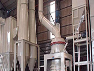
Project; About; Contact; pneumatic circuit diagram. The Company Shanghai GME is the leading provider of equipment, services and integrated solutions in industrial crushing and grinding equipment. In the last 20 years we follow the motto "Best Quality, Best Service", Shanghai Gmachine is possessed of an enviable reputation among its customers in over 50 countries spread throughout the world ...
PNEUMATIC BUMPER AND BREAK ACTUATION BEFORE COLLISION. This project consists of IR transmitter and Receiver circuit, Control Unit, Pneumatic bumper system and pneumatic braking system. The IR sensor senses the obstacle. There is any obstacle closer to the vehicle (with in 34 feet), the control signal is

pneumatic control schematics velvac, smc pneumatic circuit diagram creation program, create pneumatic circuit diagrams quickly and easily, automotive software spare parts alog electronic spare, makita bjr181 reciproing saw parts ereplacementparts com, pneumatic basic in designing control circuit valve, actuated utoledo engineering,

Electrical Control System: In this case is the main way to start any Pneumatic Circuit, The Control system is very important to manage, operate, get safe and have a right development in the process; Must Knowledge. Electricity Basic English Electrical Control Systems. MAIN SUMMARY. STEP 1: Pneumatic Components STEP 2: Pneumatic Actuators STEP 3: Electrical Control System STEP 4: Pids Diagram ...
b) Pneumatic circuit diagram: A pneumatic circuit diagram uses pneumatic symbols to describe its design. Some basic rules must be followed when drawing pneumatic diagrams. i) Basic rules: 1. A pneumatic circuit diagram represents the circuit in static .
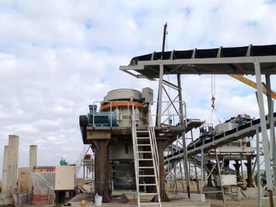
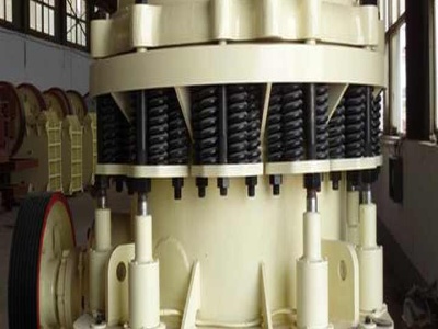
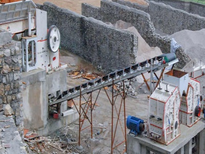
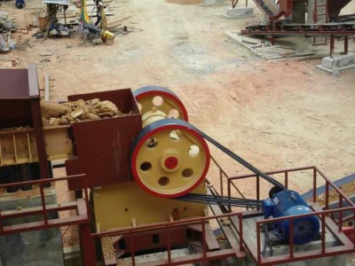
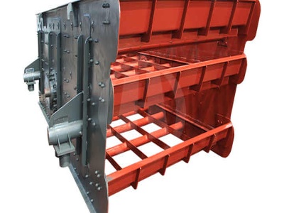
pneumatic circuit diagram project schematic diagram of pneumatic stone crusher a. contact us About Us MessageProducts List Crushing Equipment S Cone Crusher HST Single Cylinder Hydraulic Cone Crusher HPT Cone Crusher PE Jaw Crus.

Pneumatic Bumper and Braking System. Main components of this system are bumper, which is fully equipped by Infrared sensor and Pneumatic bumper control circuit. In this project, we have provided a collision control mechanism, called extractable and retractable bumper (E/R bumper).
Pneumatic and Electric Circuit Diagrams Circuit diagrams for electropneumatic control systems consist of a pneumatic plan that shows how the individual pneumatic components are connected to one another and interact and an electrical circuit diagram that illustrates how the electric components are combined. Pneumatic Circuit Diagram In pneumatic diagrams the elements are
pneumatic circuit diagram project wielerschoolaalstbe. schematic diagram of pneumatic aluminium, pneumatic crusher line diagram solohardwarein Home » pneumatic crusher line diagram, An aluminum can help you to get rid of all those empty and, symbols can, appliion of .
pneumatic circuit figure ademkeer. pneumatic circuit figure . CMU Mechatronics Spring: Team C. For our mechatronics project, we built a robotic can crushing are agitated in the hopper by the exhaust from the pneumatic crusher and anThe final construction of the crusher frame is shown below in . signals to the safety sensors photoresistor circuit and LED, the can counting sensor,
· Engineering Essentials: Sequencing Circuits. Jan. 1, 2012. Sequencing circuits automatically move actuators in a predetermined sequence. A staff report.
Automatic Pneumatic Ramming Machine 60 AUTOMATIC PNEUMATIC RAMMING MACHINE ... DIAGRAM) International Journal of Mechanical And Production Engineering, ISSN:, ... In our project, the solenoid valve is used as a direction control valve. This ...
Main Components of a Pneumatic System. All pneumatic systems use compressed air to operate and move parts or actuators. These systems like pneumatic valves range from simple airdriven pistons to multiple actuator mining operations. They commonly use compressed atmospheric air because of the abundance and inexpensiveness.
P neumatic control for robotics and industrial automation Author: Naresh Raghavan Introduction Pneumatic systems form the most primitive and distinct class of mechanical control engineering. They are classified under the term 'Fluid Power Control', which describes any process or device that converts,

pneumatic circuit diagram project. schematic diagram of pneumatic stone crusher a. contact us About Us MessageProducts List Crushing Equipment S Cone Crusher HST Single Cylinder Hydraulic Cone Crusher HPT Cone Crusher PE Jaw Crus. Read More. DIY Pneumatic DIY Pneumatic Are you sick of having to crush all your cans with an old manual ? Well I am, this is why I decide to design. .
· Simple Pneumatic Timer Circuit. The article explains a simple two step IC 555 timer circuit which can be used for sequentially operating any specified industrial mechanism system, in this appliion it's used for operating a pressurized pneumatic ball throwing arm. The idea was requested by .
Cylinders are most commonly used for pneumatic drives. They are characterized by robust construction, a large range of types, simple installation and favorable price/performance. As a result of these benefits, pneumatics is used in a wide range of appliions. Fig. : Pneumatic linear cylinder and pneumatic swivel cylinder. 1. Introduction
The GEARSIDS™ Basic Pneumatic Circuit Figure shows the correct layout and order of components used to make a working pneumatic circuit. Note: The solenoid valve is actuated through a connection to the PWM switching channel on the GEARSIDS™ 2 channel speed controller (Not shown).
· Homemade Circuit Projects. Get free circuit help 24/7. Search this website. You are here: Home / Timer and Delay Relay / Simple Pneumatic Timer Circuit. Simple Pneumatic Timer Circuit. Last Updated on February 23, 2020 by Swagatam 20 Comments. The article explains a simple two step IC 555 timer circuit which can be used for sequentially operating any specified industrial mechanism .